Heavy-Duty Columns and Crane Loads: A Practical Design Brief
Designing steel buildings that can safely handle crane loads requires more than just sizing beams and columns—it demands an understanding of how forces move through the entire structural system. In industrial environments where cranes lift tens of tons of material daily, small design errors can cause serious misalignments, deflection, or even structural failure. That’s why crane load steel building design has become a specialized discipline that integrates engineering precision with fabrication expertise.
This article explores the essential principles of crane load design, focusing on the role of columns, runway beams, and bracing systems in ensuring stability, durability, and safety for heavy-duty operations. Whether it’s an EOT crane inside a fabrication shop or an overhead system in a logistics warehouse, the same fundamentals apply: balanced load paths, controlled deflection, and solid connections between structure and machinery.
Understanding Crane Load Steel Building Design
A steel building designed to carry overhead cranes experiences unique forces that go far beyond static dead loads. Crane load steel building design must account for three major load types: vertical, horizontal, and dynamic. Vertical loads come from the weight of the crane, trolley, and lifted material. Horizontal forces occur when the crane starts, stops, or changes direction. Dynamic loads are transient forces caused by acceleration, deceleration, and vibration. Together, these create complex stress patterns across the entire frame.
In addition to these mechanical loads, environmental factors such as wind, temperature, and foundation settlement also affect crane structures. A balanced design ensures that these loads are properly distributed across columns, runway beams, and bracing members so that no single component becomes overstressed. For that reason, most industrial designers follow international standards like AISC Design Guide 7 or Eurocode 3 when developing load combinations and deflection criteria.
Key Components: Columns, Runway Beams, and Bracing Systems
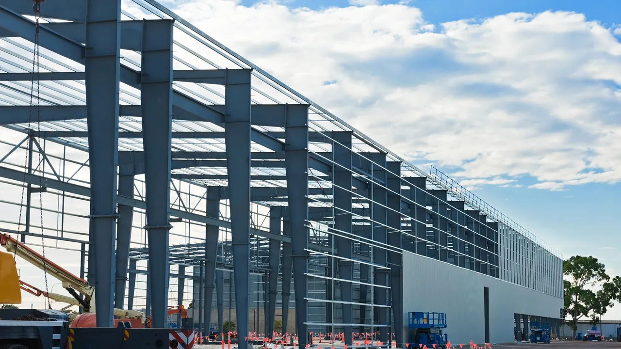
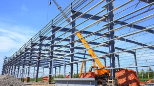
Crane-supporting buildings typically consist of three interconnected systems: columns that carry vertical loads, runway beams that transfer crane wheel loads, and bracing systems that stabilize lateral forces. Each element must be proportioned and detailed to handle both static and moving stresses.
- Columns: act as the primary load-carrying elements, transferring the combined weight of roof, crane, and structure to the foundation. In heavy-duty applications, columns are often built-up box sections or double web I-beams for added stiffness.
- Runway Beams: serve as rails for the crane’s traveling wheels. These beams must resist bending, vibration, and torsion simultaneously.
- Bracing Systems: ensure that the building maintains lateral stability. When the crane moves, the horizontal forces are transferred through the bracing network to prevent sway or twisting.
The interaction between these components determines overall performance. For instance, if runway beams are not properly aligned with column centers, the resulting eccentricity can introduce additional bending moments, potentially leading to premature fatigue or distortion. To mitigate this, designers use stiffeners, end plates, and precise welding alignment during fabrication.
EOT Cranes and Their Structural Impacts
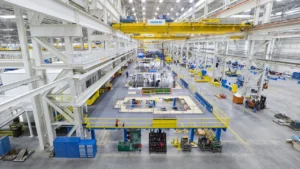
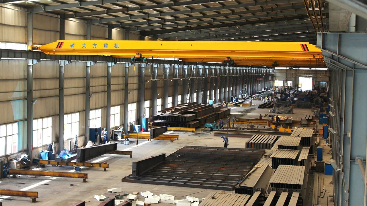
Most industrial buildings employ EOT (Electric Overhead Traveling) cranes for lifting and moving heavy materials. These cranes run along gantry rails attached to runway beams supported by the main columns. While efficient, they also exert complex and fluctuating loads on the building frame.
The key structural impacts include:
- Wheel Loads: The concentrated forces at each crane wheel can reach several tons depending on lifting capacity. Designers calculate maximum wheel loads under full capacity, including the weight of the crane bridge and trolley.
- Surge Loads: When the crane accelerates or brakes, horizontal surge forces are transmitted through the rails into the supporting beams.
- Impact Loads: Dynamic amplification factors (DAF) are applied to account for sudden lifting or dropping motions.
For instance, a 20-ton EOT crane might exert a wheel load exceeding 50 kN on each side, magnified by a DAF of 1.25–1.5. These loads must be distributed carefully across the runway beams and columns using properly designed end connections and stiffeners. Any imbalance in this system can result in alignment issues, uneven wear on crane wheels, or vibration resonance that weakens the structure over time.
Runway Beam Design Considerations
The runway beam is the backbone of any crane system. It not only supports the crane’s movement but also absorbs repeated bending and vibration. Proper selection of the beam section and connection detail determines how smoothly the crane operates.
Key design parameters include section modulus, allowable deflection, and fatigue resistance. The allowable vertical deflection under maximum load is typically limited to span/600 for smooth crane operation. Excessive deflection can cause wheel misalignment or derailment. To reduce vibration, designers often use built-up I-girders with reinforced top flanges or box sections instead of standard rolled beams.
Runway beams are also subject to torsional forces when cranes accelerate. To counter this, lateral bracing or channel ties are installed between parallel beams, increasing stiffness and distributing surge forces evenly. Connection detailing is equally important: welds at beam-column junctions must handle both shear and torsion without fatigue cracking.
A simplified comparison of common beam types used for crane runways is shown below:
| Beam Type | Advantages | Applications |
|---|---|---|
| Rolled I-Beam | Economical, readily available | Light-duty workshops |
| Built-Up I-Girder | Customizable stiffness, better fatigue performance | Medium to heavy-duty factories |
| Box Girder | High torsional resistance, ideal for wide spans | Heavy fabrication plants, shipyards |
Column Design Under Combined Loads
Columns in a crane-supported building carry not only axial loads from the roof and structure but also horizontal and moment forces from the moving crane. A typical column may experience bending in two directions—one from the crane runway and another from lateral sway or wind pressure. Therefore, column design must include checks for combined stress conditions.
Common issues include load eccentricity between the runway beam and column web, or horizontal thrust generated by crane braking. To strengthen the system, designers often adopt built-up box columns with internal stiffeners or dual-web designs that increase rigidity. Additional bracing between columns, either through knee braces or cross-braced panels, further minimizes deflection and lateral drift.
By combining strong cross-sections with precise fabrication tolerances, engineers ensure that the crane operates smoothly and safely under repeated heavy-duty cycles.
When it comes to real-world implementation, the connection between structural design and fabrication becomes critical. Close coordination between the engineer and the fabrication team—especially those experienced in heavy steel structure fabrication—ensures that every weld, stiffener, and gusset plate is placed exactly where it should be to handle dynamic crane loads effectively.
Bracing and Lateral Stability in Crane Buildings
In a structure subjected to heavy moving loads, bracing is the hidden hero that keeps everything stable. The moment a crane accelerates or stops, horizontal forces ripple through the frame. Without a proper bracing system, these forces could cause sway, alignment issues, or even buckling of slender columns. Therefore, effective bracing is a core requirement in any crane load steel building design.
There are several types of bracing systems used in crane buildings:
- X-Bracing: Offers excellent stiffness and is ideal for long bays where lateral forces are significant. Often applied between columns or along wall frames.
- K-Bracing: Provides partial lateral support while maintaining open space for doorways or equipment zones.
- Portal Bracing: Commonly used near crane runways or overhead platforms where access clearance is needed.
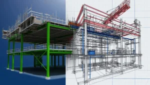
In practice, bracing design involves balancing stiffness and flexibility. Too stiff, and it can create unwanted stress concentrations; too flexible, and deflection may exceed limits. Engineers often perform finite element simulations to verify how the structure reacts to dynamic crane forces before finalizing bracing layouts. A well-distributed bracing system prevents frame distortion and helps maintain consistent crane alignment over years of service.
Practical Detailing for Heavy Steel Structure Fabrication
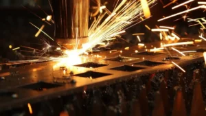
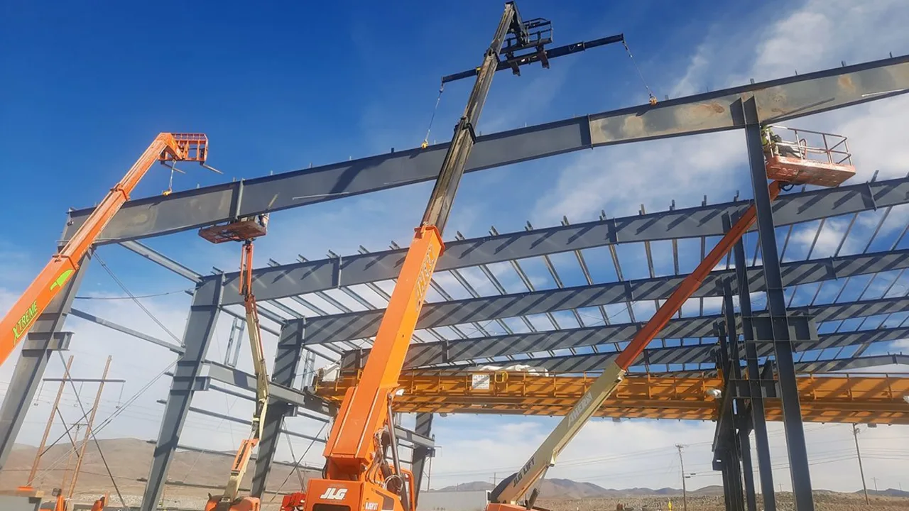
Beyond structural calculations, detailing plays an equally critical role in the performance of crane-supporting buildings. Every weld, bolt, and joint transfers forces that can multiply under motion. The detailing process must therefore consider both strength and maintainability. During shop fabrication, high-precision jigs and fixtures ensure that beam flanges and column faces remain perfectly aligned to the crane rails.
Fabricators specializing in heavy steel structure fabrication understand that even small deviations—like a 2 mm offset in runway elevation—can lead to crane wheel misalignment and increased wear. Using advanced CNC cutting, robotic welding, and laser measuring systems helps eliminate these errors. Proper weld sequencing minimizes distortion, while careful grinding ensures smooth bearing surfaces for crane rail plates.
During installation, the interface between the structural frame and crane rails requires meticulous attention. Expansion joints, shim plates, and alignment bolts must be positioned so that any movement or thermal expansion doesn’t cause long-term stress buildup. Close collaboration between the design engineer, fabricator, and crane supplier ensures that each component integrates seamlessly into the larger system.
Common Design Challenges and Solutions
Even with the best design intentions, real-world projects often face challenges. The most frequent issues encountered in crane load steel building design include:
- Excessive deflection in runway beams: This can cause uneven rail levels and noise during crane movement. Solution: increase beam depth or use composite box girders for better stiffness.
- Misalignment of crane rails: Often a result of cumulative fabrication tolerances. Solution: implement laser-guided alignment during installation and periodic inspection.
- Structural resonance: Vibration caused by repetitive crane motion can lead to fatigue. Solution: introduce damping devices or modify bracing frequency to shift the resonance range.
Another challenge lies in the trade-off between cost and rigidity. Oversized members guarantee safety but raise material costs, while undersized designs reduce weight but risk long-term deflection. The key is to find a balanced configuration through iterative modeling and stress simulation. A combination of accurate design, quality fabrication, and precise erection delivers the most efficient result.
Safety and Maintenance Considerations
Even the strongest steel frame will degrade if neglected. Continuous inspection and maintenance are vital to keeping crane buildings safe. Regular checks include monitoring weld cracks, bolt loosening, and column base settlements. Because dynamic loads accumulate fatigue over time, any visual deformation or unusual vibration should trigger immediate investigation.
Crane runway alignment should also be verified periodically. Misalignment not only stresses the structural frame but also shortens the life of crane wheels and rails. Lubrication of moving parts, repainting of exposed steel, and inspection of bracing connections all contribute to long-term structural integrity.
Advanced facilities now use structural health monitoring sensors to detect vibration amplitude and deflection in real time. By combining digital monitoring with maintenance records, plant managers can predict wear patterns and schedule repairs before problems occur. This proactive approach reduces downtime and extends the life cycle of the entire facility.
Conclusion: Building for Strength, Stability, and Longevity
The modern industrial landscape demands buildings that can handle dynamic operations with precision and reliability. Properly engineered crane load steel building design ensures that heavy-duty cranes perform safely under repetitive stresses without compromising structural integrity. By understanding how columns, runway beams, and bracing systems interact, engineers can create facilities that are both strong and efficient.
From the design table to on-site installation, every phase must uphold precision. Using experienced teams skilled in heavy fabrication and precise erection guarantees consistent results. When fabrication accuracy, design strength, and maintenance discipline come together, the outcome is a steel building that withstands decades of rigorous crane operations with minimal issues.
Ultimately, success in crane building design isn’t defined by oversized members but by optimized systems—where every element carries its share of the load. Through thoughtful detailing, verified calculations, and skilled execution, engineers turn complex mechanical forces into a harmonious balance of stability, productivity, and longevity.